AMAZON multi-meters discounts AMAZON oscilloscope discounts
The best way to arrive at a successful solution to the problem of radio and automatic control is to analyze every possible movement, action and operation to determine exactly what is to be done and what factors affect the ultimate performance. We must make the assumption that we are looking for perfection, and that we are willing to analyze and experiment to obtain it. While many concepts can be simplified if one resorts to advanced mathematics, we shall not do so here. Our approach shall be one which we hope will stimulate thought and provide a basis for experimentation so that the ultimate may be achieved.
The effect of delays
When radio-controlling your airplane, boat or car, have you ever noted the time interval between sending commands and the time the model actually responded? Have you ever consciously thought how long that time interval is between the time when you yourself first determined that you wanted to send a command and the time you actually got the command sent? Think for a moment. The model aircraft is overhead and you see that it is heading slightly off the course you desire. You analyze this situation for a second or two and then send a corrective command by pushing a button or moving a lever. There is definitely another second or two before you see the model correct its body orientation and then start moving in the desired direction.
If you send the command an instant too long, which is so often done, then the model corrects too far and you find it in error again. You send another command. The flight of the model becomes an oscillation ...
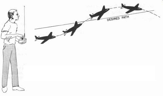
Fig. 101. System and human delays cause oscillation after disturbance gets
model off course.
...about the desired course, as shown in Fig. 101. We can say that the reason why this oscillation develops is the time delay or lag in response to our control system. Note that, when we speak of our control system here, we are including our own performance as well as the transmitter, coder, receiver, decoder, servomechanism (servo) and model.
The basic control loop
The magnitude of this oscillation, caused by delay, is directly related to the speed and maneuverability of the aircraft. With a large, ultra-stable model, flying at low speeds, it is possible that the person control ling the airplane can, after some practice, learn to anticipate the model's response. Anticipation is the ability, when the model heads off course, to send a command that corrects the control settings so that the model does not overshoot or oscillate about the desired flight path.
This is the reason why expert fliers are able, with exactly the same kind of airplane, to out-fly those with less experience or those who do not realize the need for this anticipation. There is always a breaking-in period with a new airplane as the controller or pilot learns how it reacts and how much he must anticipate before he can make it do precisely what he wants it to.
In Fig. 102-a we see a control system loop. We see, first of all, that the pilot observes the motion of the aircraft with his eyes. We call the control element which does this job a tracker. The tracker sends information to the brain as to the speed, distance and angular orientation of the aircraft, as well as its heading.
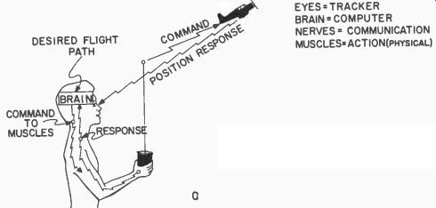
Fig. 102-a. Human model control.
The brain (the computer) analyzes this information by comparing it with previous experience (memory), and then determines what should be done. It sends a command, via the nerves, down the arm to the fingers holding the control stick. Note that there is an order of priority in the computation. It may well be that the attitude of the model must be straightened (to avoid a crash) before any positional change is effected. The original command for a positional change must then be modified in view of the new position of the model after its attitude has been corrected.
For example, let us assume that an attitude change is necessary. The brain flashes a command through the nerves down to the fingers, and the finger muscles push a button, move a lever or turn a dial, as the case may be. The brain knows that this operation is taking place, even without seeing it, because the nerves also carry information back to the brain regarding the pressure and feel of the control element against the finger tips. The brain anticipates about how much muscular reaction is necessary, and tells the fingers to stop when it thinks it has sent out the proper command. It doesn't stop there, however; it now uses the tracker's eyes for verification of its calculations. If the model's attitude isn't correct, immediately another command flashes to the fingers.
The two loops involved
Let us examine the system more closely. First, the command generated in the transmitter must be sent out via radio to the model. The receiver must pick it up and route it to the proper control mechanism.
This mechanism must move and, in doing so, move the control surfaces.
The model itself will then respond, since the aerodynamic forces now acting on the model are different. The model first changes its angular position in space; then, because of this change, moves in a new direction. It is possible to present the picture of the complete control situation, as shown in Fig. 102-b, as a servomechanism with two feed back loops. Note that the input to the system is what the human brain wants the model to do. The large loop consists of the brain, servo, transmitter, model and tracker. The small inner loop is the muscular movement of the arm and fingers and the nerve feedback to the brain.
In servomechanisms, delays can cause all kinds of trouble and mal functioning, and here we have one servomechanism loop operating inside another.
More delays Two other delays then, assuming that transmission and reception of the command are instantaneous, are the time required for the control mechanism (in the model) to move and for the aircraft to respond.
Now let's add them all up. There are the delays in the person while the brain works and the muscles move, and there are the two delays
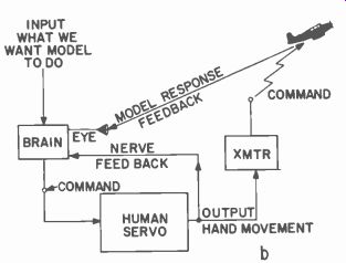
Fig. 102-b. Servo diagram. Internal and external feedback are required.
in regard to the model itself and its servo. Is it any wonder we generally lag a little when we try to control a reasonably fast aircraft? And is it any wonder that identical aircraft, with identical control systems, give different performances when different individuals control them? Brain and muscle responses can differ largely and the effect can mean the winning of a contest.
In a servomechanism, each part is tailored for a specific performance in a specific system. However, one cannot easily modify his own ( human) servomechanism. For best over-all performance, then, one must tailor the control system and aircraft to fit one's human servo mechanism. This might mean some modification of the models them selves; it might mean a different type of control system than a friend uses. Primarily, it means you should experiment to arrive at the ultimate, the best, for your individual case. This is the reason why the experts who take home the trophies modify or adapt standard equipment or build their own.
Improving the human servo
Delays, when they are large, can put a model into oscillation. A simple experiment will prove the point. Take a pendulum (which can be likened to the controlled body), swing it and, watching carefully, tap it at such a time and position that you make it stop swinging.
This is easy if the pendulum is long and the swing slow. Make the pendulum shorter and the difficulty increases. The swing becomes faster the shorter the pendulum gets. You may find that you will tap it at such a time and in such a direction that you help the swing rather than stop it.
In aircraft, this analogy applies to large and stable models versus small, fast, highly responsive types. What does this prove? It means that we should get faster responses from every part of the big servo loop. We must have very fast responses from equipment, and we must improve ourselves by practice.
The probability of success
Let us now examine the control system's reliability. Reliability is defined here as the percent chance that any unit, or the complete control system, will operate properly during any particular flight or control operation. If a system is 100% reliable, everything should function correctly each time we fly. There will never be any bugs; we will always get the correct response to every command, and each command will be exactly the one wanted for that situation.
In computing reliability, the number 1 stands for 100%, 0.5 for 50%, 0.1 for 10%. A number like 0.5 means we have a 50-50 chance that everything will operate as it should. Normally, the figure should be larger than that. A good figure to shoot at, considering human errors too, would be 0.8 or higher.
Another interpretation can be made if the reliability figure is 0.5 (50% ). One half the flights of the model will be perfect and the other half will have malfunctioning of equipment, model or pilot. Note that the word "malfunctioning" does not necessarily mean a crash.
How do we calculate the probability of successful radio control operations? We merely assign a reliability number, a decimal fraction, to each part of the system, and multiply them all together. Let's try an example.
Assume that you know the motor of the airplane will run as it should 90% of the time. We assign it the number 0.9. Assume that the model will fly as it should 90% of the time (0.9). Also assign the 90% factor to the receiver, transmitter and servo individually. This is shown in the block diagram of Fig. 103.
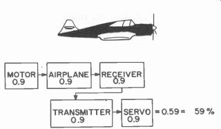
Fig. 103. In reliability, major parts of radio control include model. Reliability
factor is product of terms.
The over-all probability of success, then, is the product of all decimal fractions:
Motor Airplane Receiver Transmitter Servo
0.9 X 0.9 X 0.9 X 0.9 X 0.9 = 0.59049
This means that we have about a 59% chance of success every time we go out to fly and radio-control our model (0.59 X 100). Is it any wonder then that sometimes we do have failures? We can analyze each part of our system in terms of how successfully it operates and try to get each part as nearly 100% reliable as possible.
With the control system, for example, we might send 1,000 commands at the average range of operation and see how many are executed correctly. (This is a kind of range test.) We say 1,000 because the more commands we send to take our sample from, the more accurate our individual reliability figures will be. The reliability factor then is:
Number of commands correctly performed / Total number of commands sent
If this figure, obtained by the calculation above, is- low, then we should work to improve our system before putting it into operation in the model. Note that we have not shown a method of actually calculating human reliability. We will let you estimate how accurately you think you observe and how often you send the right command, at the correct instant, out of 1,000 operations while a model is in flight. Is your rating high? Whatever it is, be sure to include it in the final computation of the over-all system reliability.
Improving the probability
How do we improve our chances of success? First, we must have a model, properly designed (as most manufactured models are), and second we must build it exactly as the manufacturers have specified.
When changes are made, we must know what we are doing. Manufacturers have spent countless months testing and checking their models to make them as foolproof and reliable as possible. Yet how often do we build carelessly, make modifications that add too much weight, balance incorrectly and use too small or too large motors or propellers? A big percentage of failures and a low reliability factor for the model itself can be attributed to these causes.
This seems in contradiction to a previous statement that we should tailor the model to ourselves. It isn't. We should take advantage of the high reliability in the design efforts of the manufacturer first; then, with accumulated experience, we can make such modifications as we feel are necessary. Build an airplane exactly as specified. Fly it until you know it like the palm of your hand; then make the changes, little by little, very carefully, so that it becomes tailored to you as an individual.
With the control equipment, we must again take care to read and understand the specifications which most manufacturers furnish. Do not exceed ratings or attempt adjustments which require equipment you do not have. Take advantage of the installation and checking procedures and make sure to use the equipment in the same environment as the one the manufacturers have tested and adjusted it for.
Again, study your equipment until you feel that it is a part of you, until you know its weaknesses. After that, never modify it unless it becomes absolutely necessary. A good rule here is: "When it's working right, keep your fingers out of it." Reliability consciousness dictates that we must build equipment ruggedly and foolproof--not build with the idea of just wiring some thing together to make do. Always plan and build as though you expect to have your equipment held up as an example of a work of art, as though you expect it to last for many, many years without repair or adjustment. Take care in the selection of components, in soldering, in layout, in making good mechanical and electrical connections and in producing equipment that has a factory-like finish. You will then find your reliability factor nearing that 100% mark.
In the field of guided missiles, rockets and satellites, it was once thought that, since most of it is a one-shot object, equipment that would last for just one mission would be good enough. It has since been proved that, if a missile system is to be reliable for those few minutes of operation, it must be built as though it were expected to operate for years! A friend once overheard an argument along these lines and, shaking his head he moaned, pointing to his model: "That means that it should be designed to last for centuries." Practice will improve judgment and reaction time. With human engineering we can also improve the mechanics of the control system so they are best suited to an individual and there will be less margin for error. The physical shape, size and location of the controls should be tailored individually for optimum performance. Since there are physical as well as mental differences in people, a person who is large and muscular may have an inherent distaste for small, delicate knobs, levers and buttons. He may want controls he can grasp firmly, that require some strength to move and that feel good and solid.
Another person may want small levers, knobs, buttons and dials and, of course, everyone will have preferences as to whether the controls should be grouped together, separated, operated with one or both hands. There will be preferences as to whether the control box should be hand-held, mounted on a panel, held at waist level or shoulder height. The very type of control may make a difference. A radio amateur who is at home grasping the knob of a telegraph key may not feel at home pushing a button. His reactions may be slowed. Yet both devices do exactly the same thing-make or break an electrical circuit.
So, again, to improve the human reliability, tailor the equipment to yourself. Determine the motions you are used to and determine the knobs and dials you can use most easily.
Control codes
Much has been written about the general types of control systems; the single channel, in which compound servos or escapements enable you to have control over many functions and the more elaborate multi channel types. Some of the multichannel types presently offer simultaneous and proportional control of sorts. Even the single channel types offer in pulse-width, pulse-spacing applications simultaneous control over rudder and elevator. With pulse-rate variations added, a third function can be controlled.
In this text we are primarily interested in ideas applicable to the simultaneous-proportional control problem. Let us begin with a consideration of coding, or methods of sending intelligence.
The following list covers the most obvious advantages and disadvantages of several methods:
a. Combination pulse width and rate for control of two elements This has been successful in many applications. Its disadvantage is that it allows control over just two elements.
b. Simultaneous transmission of two tones We say two tones because this is the normal number used without interference. We can control two elements with this system using any combination of tones as long as only two are transmitted simultaneously and as long as these two are well separated to prevent crosstalk or channel spillover.
c. Simultaneous transmission of two varying tones Here discriminators are used in the receiving equipment to obtain proportional control. As of this writing, only single channel systems (in other words, one varying tone controlling one element) have been very successful. Transmission of two varying tones simultaneously would allow control of two elements.
d. Pulse codes This type of system has not, to our knowledge, been investigated fully in the model field. While pulses would not be transmitted simultaneously, if their transmission spacing were very short compared to the response time of the equipment, they could be considered as a method of simultaneous control.
e. Pulse position jitter This method, well-known in telemetry, is another application of pulse codes.
These methods can be sorted into two basic categories : pulses and tones.
Pulses vs tones
To control a model with a proportional control system using tones, consider how many tones must be transmitted simultaneously, received and decoded. Since the control operations include motor, rudder, elevator and ailerons, a maximum of four tones at any one time are required.
Suppose we transmit a tone. Let's assume our transmitter is 100% modulated by this one tone. All the power in the carrier sidebands is due to this tone and when the signal is detected in the receiver, the tone amplitude depends on this sideband power.
If we send two tones simultaneously, then this sideband power must be divided. Less is now available for each tone. This means less power in each recovered tone. Three tones would allocate even less sideband power to each and four tones would have still less usable sideband power.
To be able to recover modulation with rather good decoding equipment there should be at least 12.5% modulation at the transmitter.
This sets a maximum of eight tones to be transmitted simultaneously on any one carrier frequency.
We know the super-regenerative receiver works best when it receives a 100% modulated signal. It produces its strongest tone output at this level. Since its detection curve is exponential, we can expect a sharp drop-off in recovered signal level with each additional tone to be trans mitted. The output of the detector in a superheterodyne (superhet) receiver is also affected by the percentage of modulation of the trans mitted signal but the linearity of the diode detector of a superhet is much better than the detector action of a super-regenerative receiver.
The superhet works better when simultaneous multi-tone modulation is used, especially when more than two tones are involved. The method of simultaneous modulation is also known as the modulation-sharing type.
Pulse modulation
A transmitted pulse can be 100% modulation--it can occupy the whole carrier level if it keys the carrier pulse on and off. Think of pulses in terms of trains or sequences of pulses being transmitted at a very rapid rate. These can be used to get the same effect as simultaneous transmission without the disadvantage of low modulation as in the modulation-sharing situation. A pulse train could be 15 pulses of short duration, for instance, with a definite spacing between each of them, following a marker pulse--a pulse of longer duration to show the starting of each pulse train. The marker might also be a pulse at a different tone or frequency. Its sole purpose would be to reset a decoder in the receiver. Now we can send 15 commands-good, strong commands each using the full 100% modulation--and if we can transmit the whole train in a fraction of a second, the fact that they are sequenced will present no model-control delay problems.
This method is called pulse-time modulation, the time sharing method, since each pulse occupies a part of the transmitter's ON time.
The decoding problem
Perhaps the greatest difficulty in achieving multifunction, simultaneous and proportional control is in designing a suitable decoder to perform the function separation task for us at the receiver. The problem of combining many tones simultaneously or of generating pulses which can convey the necessary intelligence, is a minor one. We have no limitations as to the size, weight or space required for ground-based transmitting equipment. It can be complex and built to perform reliably. The real problem is in the decoder at the receiver, because we are concerned with size, weight, current drain and reliability. In the past, this problem has been almost insurmountable, but now, with subminiature and microminiature parts, small, reliable decoders are feasible.
In every decoder there is some sort of switching device. This may be a relay, a diode or a transistor. For slow speed controls, adjusting the pull-in and drop-out operating points of the relay has been highly satisfactory.
However, when one deals in fast pulses ( used in high-speed control), sparking, contact bounce and short contact time are troubles frequently encountered with relays. Sparking, for example, can produce signals similar to the pulses sent as control signals. Obviously we don't want this.
Let's look into this a little further. Throughout the control field we run into problems brought on by the mass of a moving object (such as a relay armature), the friction generated and other forces both acting on and generated by the object.
Mass has to do with the weight and density of a material. It is, in fact, the weight divided by the gravitational constant (32.2 ft/sec/sec ). Mass gives rise to the concept of inertia. Inertia is that property of a body which tends to resist motion, but, when the body is in motion, it tends to make the body keep moving. An automobile has mass. Try to push it and you find it resists being moved. Get it rolling and you have trouble making it stop. Of course, there is friction involved due to the tires pressing against the pavement and the weight on the axles.
Now consider an armature of a relay. It also has mass, and therefore inertia. Spring tension and a magnetic field ( when energized) oppose each other and cause the armature to move. Friction is involved. Put all these together and what do we have? First, consider the relay de-energized. Suddenly the circuit is closed, applying the magnetic field.
The armature is set in motion. It doesn't want to move, because of its mass; the spring doesn't want it to move either, but the magnetic field, being stronger, makes it move. Once it is moving, the armature doesn't want to stop. It hits a solid contact and bounces. The controlled circuit is broken and then made again as the armature is pulled back by the magnetic field. Then, when the control circuit (magnetic field circuit) is broken, the spring pulls the armature back.
If everything is properly designed, and by this we mean the mass of the armature, the strength of the spring, the strength of the magnetic field, the friction of the bearings and, if the contacts are designed to give a little during the first impact, the armature will bounce without actually breaking the circuit. The relay, then, has been designed with the proper balance between mass, friction and the forces involved. There is also air resistance to the armature motion, which we have not considered here, nor have we considered the pull of gravity on the armature.
As you can see, (in the decoding problem where high-speed switching is required), if relays are used, they must be carefully designed.
Decoding problems become more complex as we improve our capability to control, and we are fortunate that smaller components are becoming more readily available to accomplish the task. New horizons open up when we investigate electronic decoding.
Mass-friction---forces on an aircraft Now that we have introduced the concepts of mass, friction and force in connection with a relay, let us look for a moment at the air craft. It, too, has these phenomena.
FORCE DUE TO AIR RESISTING ROTATION (DAMPING) ROTATION CENTER GRAVITY DISTURBING START OF OSCILLATION
OSCILLATION UP AND DOWN MOTION OF STABILIZER
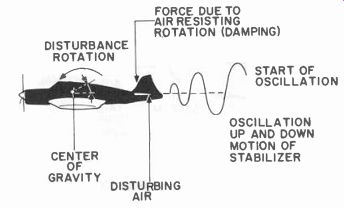
Fig. 104. Model mass tends to resist motion, but when motion is started, mass
wants to keep moving, resulting in oscillation.
Fig. 104 shows a profile of a typical model. Everything is measured with reference to its center of gravity or balance point. We are concerned with the motion of the tail assembly when some disturbing air, say from below, momentarily whips the tail up higher than it would be in normal flight. Note the direction of body rotation about the center of gravity due to this disturbing air (force).
Again we are concerned with mass and inertia. The aircraft tends to resist the motion, but once moving tends to continue. We are concerned with friction, the resistance of the air to the tail surface moving up (this is a damping effect), and we are concerned with the restoring force, the force on the tail due to the airstream from the propeller hitting the tail at an angle.
The graph of the stabilizer position shows that it oscillates up and down, but a smaller and smaller amount each time, until the tail settles into its normal flight position. The physical part of the aircraft which made this oscillation die down quickly is the surface area of the stabilizer which directly determines the damping force. Thus we can see that an aircraft with a small stabilizer area might tend to oscillate longer than one which has a larger area.
There is another way in which this oscillation may be damped and that is with the control system. First let us assume that we have an aircraft with a medium-size tail surface and that we send it an up signal, using an escapement or a servo, which whips the elevator to the up position hard and fast. Let us assume that when the higher altitude is reached, we release the signal and let the aircraft level off.
CG=CENTER OF GRAVITY
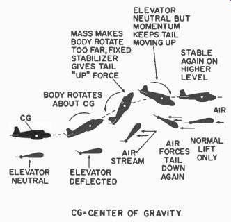
Fig. 105. Response of aircraft to "bang bang" elevator signal.
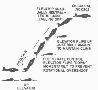
Fig. 106. Gradual deflection of elevator will prevent oscillation.
The picture is shown in Fig. 105. Notice that the quick deflection of the elevator is similar to the disturbing air of our previous case. The body quickly changes its angular orientation in space, and actually turns too far. When the elevator is released to neutral, the high angle of attack of the stabilizer, due to the body turning, produces a tremendous restoring force which whips the tail high. Then we have oscillation until the natural weather-cocking of the model stabilizes it at the higher altitude.
One term in the equation is affected by our control system when we have damping built into the system. In this case, the damping is a control signal which can be sent at the right time calling for the right amount of elevator deflection to prevent this oscillation. Fig. 106 illustrates this case.
In Fig. 106 we see that again we deflect the elevator for UP. This time, however, we have deflected the elevator just the right amount for UP, using a proportional control system. The body rotates as before, but now instead of overshooting the vertical climb line, note that when the correct climb angle is reached, the elevator deflects in the opposite direction to prevent further rotation.
The amount that the elevator deflected in the down direction would have been directly dependent on how fast the body was rotating (angular velocity). For a very slow rotation, the elevator might not deflect down at all, while for a very fast rotation, it would deflect a large amount.
Again, at the new altitude the elevator gradually neutralizes to level off, or if a fast leveling off is required, it would deflect first into the down and then the up position. This is the way autopilots in large aircraft work. That is why these aircraft fly so smoothly.
The question is--can we incorporate rate control, as this type of control is called, in model aircraft? We do insert a kind of rate control when we anticipate a model's maneuvering in normal flying. Perhaps we should consider the use of a rate signal (generated in the model servomechanism) to get smooth, proportional rudder, elevator or aileron deflections and get them quickly. This type control would improve any contest-airplane system and would insure control over very fast flying models.