AMAZON multi-meters discounts AMAZON oscilloscope discounts
One way to increase reliability is to reduce the number of parts in a control system. The fewer parts we have, the less perfectly each has to operate to achieve a given figure of success. For example, two parts each with a 0.9 reliability gives 0.81 or 81% for the system. Four parts with the same individual reliability would give 0.9 X 0.9 X 0.9 X 0.9 = 0.656, or about 66% chance of success.
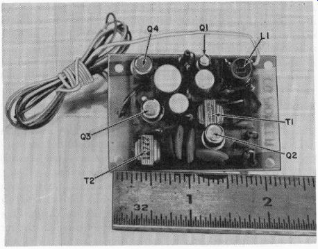
Fig. 201. Top view of superregenerative receiver. Set uses transistors only.
In this section we will discuss the relay-less and the superhet control receivers. The first is an example of reduction of parts--no relay.
The second has many parts but each part has a reliability factor of very nearly 100%. These are proven receivers, and both are tone-operated. We shall discuss their operation, effects of adjustment and some theoretical considerations.
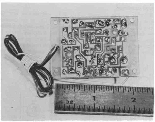
Fig. 202. Use of printed circuits reduces amount of wiring to be done.
The relayless superregenerative receiver Fig. 201 shows a picture of this receiver. Note the small relative size. Wiring is reduced through the use of printed circuits, as shown by Fig. 202. The circuit schematic is shown in Fig. 203. This receiver uses transistors for the superregen detector and audio stages. Another transistor is used in place of the relay normally found in the output of control receivers. The particular advantages of this unit is that it is quite immune to engine vibration and there are no relay contacts opening and closing to generate spark interference.
Since the transistor replacing the relay is tone-operated, there is additional immunity to noise pulses. When two flashlight cells are used to provide the 3 volts needed to operate the receiver, there is usually sufficient current capacity to operate the other control circuits in the model from the same source.
Circuit operation
Referring to the schematic ( Fig. 203), we examine first the circuit of Ql. The coil (L1) and capacitor (C2) in the collector circuit determine the frequency to be received. When current initially flows through these elements, the tuned circuit is shocked into oscillation. Some of this oscillatory signal is coupled back into the emitter circuit and regeneration takes place. Regeneration continues until the emitter current charges C5 to a voltage high enough to stop the ...
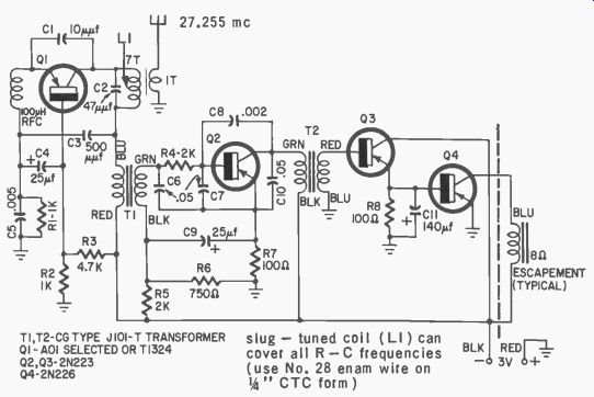
Fig. 203. Circuit of the superregenerative receiver. Relay normally used in
output circuit, is replaced by to ne-operated transistor. [Pioneer Receiver-C
G Electronic Corp.]
... oscillations. C5 then discharges through R1 and the whole action starts to build up again. C5 and R1 thus govern the quench frequency or the number of times per second that the detector stage oscillations are turned on and off.
As with most types of superregens, there is an energy burst sent out from this detector each time it is ON. These random bursts, when no signal is being received, result in the familiar hiss which we can hear in the earphones. When a signal is received, the bursts occur in a uniform manner related to the tone frequency, the hiss vanishes and we hear the tone. Note that while the signal is being fed back from collector to emitter during an oscillatory cycle, it is also being amplified.
This type of detector can produce a signal amplification of up to a million times the signal strength received at the antenna.
The tone detected is then coupled through transformer T1 to transistor Q2. This second transistor is a temperature-stabilized audio amplifier which increases the signal level still further. C7 and C10 remove the quench or other radio frequency signals that might be present so that the tone is as nice and pure as we want it to be.
Transistors Q3 and Q4 are connected in cascade so that the current change through Q3 is amplified by Q4. At the base of Q4 we are no longer interested in the tone signal, but rather an average current which is developed from the tone. This base current can control the large current in its collector-emitter circuit to operate an escapement without the use of a relay.
The primary consideration, then, is that this receiver be simple and straightforward without moving parts. Its disadvantage lies in the type of detector itself. This detector is inherently broadly tuned which means it can receive interfering signals if another tone transmitter is tuned close to its operating frequency. However, in some control applications, this broad tuning is a good feature in that the receiver will not detune and lose its control transmitter signal easily.
The superheterodyne receiver
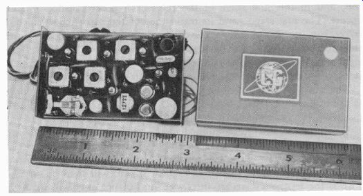
Fig. 204. Compact superheterodyne receiver uses miniature components.
The small size of this receiver (Fig. 204) has been made possible by the development of the transistor and the other miniature components. It is little larger than the superregenerative receiver in Figs. 201 and 202 but with much better performance.
The way in which a superhet detects a radio signal and converts it into a sound which can be heard, assuming of course that a tone-modulated signal is transmitted, is quite different from that of the superregen. The superhet's operation can be better understood by referring to Fig. 205.
It will reject interfering signals from transmitters tuned to frequencies very close to that of the transmitter from which it gets its control signals. This circuit will also deliver a much purer tone to the amplifier circuits because of the better linearity of its diode detector.
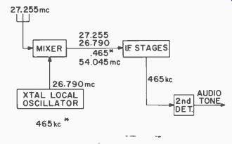
Fig. 205. Block diagram of superheterodyne.
Here a 27.255- mhz signal is picked up by the antenna and tuning coil, and in this first stage of the receiver a process called mixing occurs. The first stage (and its transistor) of the superhet is called a mixer because it not only receives the transmitted signal from the antenna, but also a signal from what is called a local oscillator. This local oscillator is very similar to the oscillator used in the transmitter.
It has a crystal to keep its signal set exactly to a certain frequency.
The purpose of the local oscillator is to generate a signal very close to the transmitted signal. Note in Fig. 205 that its frequency is 26.790 mhz, only 465 khz lower than that picked up by the antenna.
When two signals are combined in the mixer two new signals are produced giving a total of four. To simplify matters, imagine, as shown in Fig. 206, that we have a 4 cps local oscillator and that our input is 3 3/4 cps. The difference signal, or beat signal, will then be 3A cps.
This is the frequency we are interested in, but not only will we have the difference frequency, but a sum frequency as well, plus the original input and local oscillator frequencies. For the 27.255- mhz receiver we will have:
a. 27.255 + 26.790 mhz (54.045 mhz)
b. 27.255--26.790 mhz (0.465 mhz, or 465 khz)
c. 27.255 mhz
d. 26.790 mhz
Each of these four signals will contain all the intelligence which was present in the original 27.255- mhz signal. We are interested only in the 0.465- mhz (465 khz) signal which is the difference between the antenna and local oscillator signal. This is the 465- khz intermediate frequency.
The i.f. signal is then separated from the others by sending all four through another tuned circuit. This circuit is tuned to the wanted 465 khz and, just as the antenna tuning coil rejects all signals to which it is not tuned, this circuit rejects all signals but the selected one of 465 khz.
To amplify this i.f. signal, several transistors and tuned circuits are required. The i.f. signal is then sent to a transistor or a diode detector ...
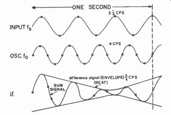
Fig. 206. Plot of result of mixing local oscillator and input signals. A low
frequency was selected for clarity.
... (which is also called a second detector since it now separates the tone from this lower radio frequency signal). The audio or tone amplifying circuits following the second detector are similar to those used in a superregen type control receiver which operates on tones.
Superhet selectivity
First of all, note that the local oscillator frequency is controlled with a crystal. The only control signals with which it can combine to produce a difference frequency of 465 khz are 27.255 and 26.325 mhz.
The receiver antenna tuning circuit will reject the 26.325- mhz image signal (if it is not too strong), leaving only the 27.255 mhz signal.
The i.f. tuned circuits in this superhet are so designed that a signal which is only 2 khz higher or lower than 465 will be amplified only seven-tenths as much as the designed signal. The bandpass is defined by this value of amplification and the bandwidth is said to be those frequencies amplified from maximum down to this 0.707 value. Note that signals which are 3 khz higher or lower than 465 khz (Fig. 207) are...
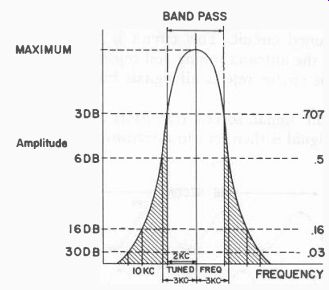
Fig. 207. Receiver selectivity curve.
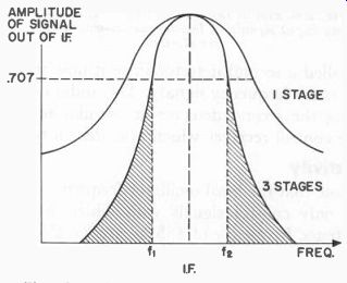
Fig. 208. Effect of a number of i.f. stages. The bandwidth is the frequency
separation between the .707 points on the curve [f1 to f2 for the three-stage
amplifier]. Note how much broader the single-stage bandpass would be.
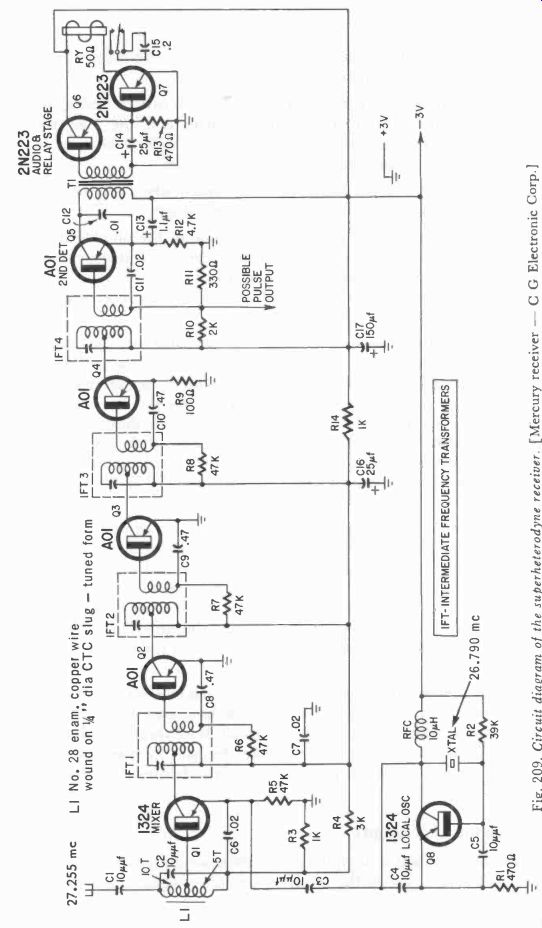
Fig. 209. Circuit diagram of the superheterodyne receiver. [Mercury receiver--CG Electronic Corp.]
...amplified only half as much (0.5) and signals 10 khz off will be amplified only 1/6 (0.16) as much as the exact frequency.
The Q (figure of merit) of the i.f. transformers is the major factor that governs the bandpass (selectivity) of the receiver. The Q of the transformers depends on the size and type of wire, core material and other mechanical and circuit variations.
The selectivity of the receiver is governed by the care in tuning the transformers, the method of coupling to them and the load the respective transistors put on their tuned circuit as well as the number of tuned circuits (transformers) in the i.f. amplifier.
Fig. 208 shows how the bandpass is broadened when only one i.f. stage is used compared to an amplifier of three stages.
The circuit schematic is in Fig. 209. Because of the amplification obtained in the i.f. amplifier only a transistor detector and relay stage are required for good reliable control operations. This receiver, like the preceding one, requires only 3 volts for operation. The detector ( Q5) also amplifies.
The local oscillator frequency in a crystal-controlled receiver cannot be varied without changing its crystal and will receive one frequency only. It is possible to change the tuning of the i.f. transformers to receive a signal of a different frequency, or to tune the receiver to a transmitter which may have a crystal frequency a little different from that furnished by the manufacturer of the receiver. If the i.f. tuning is changed from, say, 465 to 475 khz, and the local oscillator frequency is not changed, then the incoming signal will be 27.265 mhz instead of 27.255 mhz.
The Q of the i.f. coils may change when they are adjusted to this new frequency. Using the curve of Fig. 208 we could say that when the i.f. amplifier is adjusted to its design frequency, its bandpass curve is similar to the curve shown for three stages. When the i.f. transformer is tuned to a nearby frequency, its Q may change; then the curve broadens as for one i.f. stage in this figure. Arbitrarily changing the i.f. frequency could result in reducing the receiver's ability to reject unwanted signals.
To get optimum efficiency you must peak each one exactly. If each stage is slightly off tune, then the bandpass broadens (Fig. 210) so that all signals between f1 and f3 are received. If all three are adjusted so that all curves coincide, not only does the gain increase, but the bandpass narrows down to amplify only those frequencies between fi and f2.
How are the i.f.'s tuned?
A common method to align the i.f. amplifier would be to remove the crystal from its socket in the receiver, connect a signal generator to the antenna terminals and set it exactly to 465 khz. A sensitive meter' could be connected across the load resistor (R11) for the second detector Q5, and each i.f. transformer, would then be adjusted, in turn, for a maximum indication on the meter, readjusting each i.f. transformer several times after the first attempt.
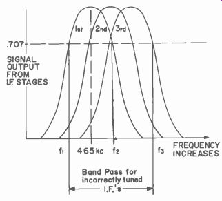
Fig. 210. When stages are stagger-tuned [all not tuned to same frequency]
bandwidth goes [from 11-12 to 11-13]. This lets interference come through.
The manufacturer of this receiver does provide a method whereby, in a case of absolute necessity, you can adjust the i.f.'s in the field, using a matching frequency transmitter (one designed to operate the receiver) and a 100-ma dc (full-scale) milliammeter. The procedure is as follows:
1. Connect the meter in series with one of the battery leads. You should get a reading of 3 to 5 ma.
2. Key the transmitter. You should note a reading of about 35 ma.
3. Remove the antenna from the transmitter, hold the key down and have an assistant move the transmitter away until the reading drops to 15 ma. Now, holding the transmitter absolutely stationary at this distance, adjust the i.f. transformer slugs in their order (1, 2, 3, 4) for maximum meter readings.
4. Move the transmitter further away until the meter readings drop to 10 ma. Readjust the i.f.'s again in the same order for maximum reading.
[ 1 .Use a vom [volt-ohm-milliammeter] or preferably a vtvm [vacuum-tube voltmeter]. Set the instrument function selector to read dc volts and the range selector at or near its maximum counter clockwise position.]
5. Repeat step 4, using extreme care to get the absolute maximum reading.
6. Place the cover on the receiver and, using a plastic tuning wand, tune the rf coil for maximum meter reading. The receiver must be connected to the antenna you plan to use during this last adjustment.
Double conversion
There is a possibility that increased selectivity (or much higher frequencies than those presently allocated) will be needed for radio control purposes.
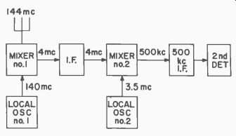
Fig. 211. Block diagram of double-conversion superheterodyne.
We have seen how a local oscillator signal can be combined with an incoming signal to produce an i.f. signal. Double conversion simply means that we repeat this process again. Note in Fig. 211 that two local oscillators are required. To make it easier, assume that the in coming signal is now at 144 mhz. After the first mixing operation, the difference signal is 4 mhz. Mixing again, after some amplification, with a local oscillator signal of 3.5 mhz produces an i.f. of 500 khz which then can be amplified in a second series of i.f. stages and fed to a detector as before.
There is also need in the superhet circuit for automatic gain control (agc). This is an electronic adjustment of the amplitude of the output signal so that it always stays at about the same level. After the i.f. signal is detected, a part of this signal can be filtered to remove all variations in level due to the transmitted signal. This dc voltage then has a magnitude which is directly proportional to the strength of the carrier signal. If this voltage is fed back to the i.f. stages in such a way that the larger it is the less the i.f. stages amplify, we have automatic gain control. Strong signals will not be amplified as much as the weaker ones. This would allow operation of the receiver close to a strong transmitter and also at a distance with the best possible performance. There would be less blocking due to circuit saturation from a too-strong signal.
Crystals, too, can be used in the i.f. stages to produce selectivity curves so sharp that signals more than a few cycles away will be rejected. Better selectivity is important when we want long distance control or fly many models at the same time.
It is also possible to narrow the bandpass of the i.f. stages of a receiver by having a regenerative i.f. stage. With some feedback of the i.f. signal, not enough to cause oscillation, the bandpass would become very narrow and much greater selectivity would be obtained.
The superhet is well adapted to the reception of pulse signals using the carrier alone. Just as we have indicated that the i.f. signal may be filtered and rectified and used for agc purposes, so too, it can be used to control the current of a subsequent transistor stage, like Q4 in Fig. 203. When carrier pulses are transmitted, the intermediate frequency will be in pulses, the current from the transistor stage following the detector will be in pulses and these could be large enough, or be amplified further, to operate a pulse decoder directly. We are going to discuss some uses of pulses later.