Like other fully electronic components whose action simulates that of electromechanical
devices, the varactor works faster and often more precisely and simply than
its counter parts. In its basic role as a variable capacitor, for example,
the varactor will operate at rates up to several million per second-faster
than any motor-driven or hand-tuned capacitor could possibly function-and it
can provide a wider range and higher efficiency than any comparable tube or
transistor arrangement. In its more sophisticated functions, the varactor achieves
with one component ( or at most, only a few components in addition to itself)
results which other wise require numerous components and complicated circuitry.
VOLTAGE AND CURRENT RESPONSE
The control voltage for a varactor may be produced and adjusted directly for this purpose, or it may be a voltage obtained from an appropriate point in a circuit containing the varactor. Alternating current, direct current, or a mix ture of the two may be used. In any event, the varactor has no way of knowing either source or intent but responds automatically-and rapidly-to each value of voltage. This means that the a-c-operated varactor "sees" a succession of instantaneous voltages and responds to each of these as if it were a d-c voltage momentarily applied.
Steady D-C Voltage
When a steady d-c voltage is applied, the capacitance of the varactor assumes a value consistent with that voltage (see Fig. 1-8) and it holds to that capacitance as long as the voltage is maintained. The reverse d-c source sees the varactor as an infinite resistance, since the leakage current is negligible. This is a distinct advantage, as the loading of the source may for practical purposes be regarded as zero. Any d-c voltage applied to a varactor for control or bias purposes must be free of ripple, in order to obtain a nonvarying junction capacitance at each voltage setting.
Inasmuch as varactor d-c control current is practically zero at reverse voltages, the voltage may be applied through a fixed high resistance, as shown in Fig. 2-1, without volt age loss across the resistor. This provides an isolation resistor which eliminates the effects of hand capacitance or of capacitance in the voltage source which would otherwise shunt the varactor. In Fig. 2-1, V is the adjustable, steady d-c voltage, R1 a high resistance ( usually several meg ohms), and X1 the varactor. A variable capacitance, corresponding to the capacitance-voltage curve of the varactor used, is obtained at terminals X-X. If the circuit or device in which this variable capacitance is to be used contains a d-c voltage, the varactor must be protected from its effects (it too can tune the varactor or burn it out) by means of a

Fig. 2-1. D-c control of a varactor.
blocking capacitor, C1. The capacitance of the latter must be very much higher than the maximum capacitance of the varactor, so that X1 rather than C1 will determine the capacitance at terminals X-X. (A good rule of thumb is to make C1 approximately 1000 times the maximum capacitance of the varactor.) With very-low-leakage varactors, there theoretically is no limit to the value of isolating resistor R1. A practical limitation is imposed, however, by the time constant (t) resulting from the series connection of this resistance and the varactor capacitance (t = RC, where t is in µ,sec, R in ohms, and C in mfd). The time constant is important when the varactor must respond to the control signal within some de sired time after application of the signal. Thus, the time constant of a 100-megohm isolating resistor and 100-pf varactor is 10 msec. If the varactor must respond in a shorter period than that, a lower resistance must be used.
As explained in Section 1, the variation of capacitance in response to applied d-c voltage is nonlinear over most of its range. The graph in Fig. 1-SA, for example, shows that in one type of varactor a 2 :1 voltage shift at one point (i.e., from 25 percent to 50 percent of rated reverse voltage) produces an inverse capacitance change of only 1.31 :1, and at another point (i.e., from 12½ percent to 25 percent of rated reverse voltage) the 2 :1 voltage shift produces an inverse capacitance change of 1.18 :1. With most varactors, only a narrow sector of the response curve is linear.
Alternating Voltage and Current
While a varactor effectively blocks reverse direct current, it allows an alternating current to pass relatively freely. It is the reactive component of the varactor which transmits the alternating current. In most applications the reactance is capacitive because the inherent inductance component of the varactor is negligible. Since capacitive reactance is frequency dependent (Xe= 1/wC), the alternating current through a given varactor, for a constant a-c applied voltage, will increase as the frequency increases, and vice versa.
At a fixed frequency (reactance therefore constant), current increases as applied a-c voltage is increased. But it in creases nonlinearly. It varies in this way because varactor capacitance, upon which the reactance depends, itself varies nonlinearly with voltage. The varactor "feels" each of the instantaneous values of voltage in the a-c cycle and automatically adjusts its capacitance in accordance with each of these. (See Fig. 2-2.) Because of the nonlinear a-c response of the varactor, the waveform of the varactor current differs from that of the applied voltage, in most instances. When a sine-wave voltage is applied, for example, the resulting current usually is non-sinusoidal-that is, distorted. But it is this nonlinear a-c response which suits the varactor, as will be shown later, to such applications as harmonic generation and parametric amplification.
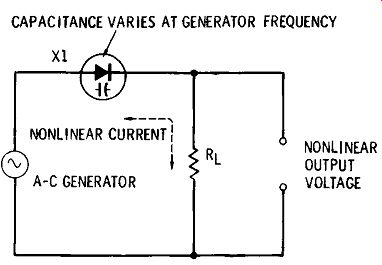
Fig. 2-2. Elementary a-c varactor circuit.
An a-c voltage presents the problem that its positive half cycles forward bias the varactor (assuming the anode is positive) ; this will ordinarily increase leakage current and voltage-source loading, lower the Q, and broaden tuning.
In many applications, therefore, care is taken to operate the varactor in such a way that it is never forward biased.
Forward biasing by the signal is not always a detriment, however. At very high frequencies, for instance, an instantaneous positive half-cycle voltage higher than the contact potential will start current carriers flowing toward the junction. But at such a high frequency the voltage is in its negative half-cycle before normal d-c forward current can be established, and this negative voltage attracts the carriers back to their starting point. The effect is somewhat similar to charging and discharging a capacitor, so virtually no power is consumed, and the reactive nonlinearity of the varactor is enhanced by the action.
The ability of the varactor to inhibit resistive current, while favoring reactive current, accounts for the high efficiency of this device in many applications. This follows from the fact that resistive current dissipates power in the resistance, and this power is lost, whereas reactive power ideally is lossless. To all practical intents and purposes, the varactor is a reactive-power device.
It must be remembered that the varactor is sensitive to all changes in applied voltage, intentional or accidental. Its capacitance therefore will vary with ripple, noise, hum, and transients. The varactor has no way of knowing that these are extraneous fluctuations. A d-c control signal or a d-c bias must be very clean. Because the varactor is a high-impedance device, hum and other interference may be accident ally capacitance-coupled into some of its circuits quite easily (as happens also in the high-resistance grid input circuit of a vacuum tube), and careful shielding may sometimes be required.
Operating Point
Through choice of a steady d-c voltage, the operating point of a varactor may be set anywhere along the capacitance-voltage response curve. Any control-voltage variation then may be accomplished by increasing the voltage above, or decreasing it below, this point. This is identical to setting the operating point of a tube or transistor by means of a d-c bias voltage.
When an operating point has been suitably chosen, an a-c signal may be superimposed on the bias ; that is, it is applied to the varactor in series with the d-c voltage. This allows operation to be placed appropriately along the varactor curve to obtain linear, square-law, or other mode of response, since the a-c signal voltage swings the bias above and below its mean value wherever the bias value is located on the voltage axis. It also permits selection of operation such that the net positive swing of the a-c signal never drives the varactor into forward conduction. Again, the technique and results are similar to those associated with tube and transistor practice.
Fig. 2-3 illustrates the effect of shifting the operating point by changing the varactor d-c bias. The sinusoidal a-c signal shown here swings from + 1 volt to -1 volt. In the first case, this signal is shown without d-c bias. As shown, the positive half-cycles then swing the varactor applied voltage up to -1 volt, and the negative half-cycles swing it across zero to + 1 volt, forward biasing the varactor during this fu L1, latter half-cycle. If, as shown in the second case, the operating point is moved to -4 volts, the positive half cycles will swing the varactor voltage up to -5 volts, and the negative half-cycles down to -3 volts, safely outside the forward bias. If the operating point were set at -1 volt, the positive peaks of this same a-c signal would swing the varactor voltage up to -2 volts, and the negative peaks down to O volt, just escaping forward bias.
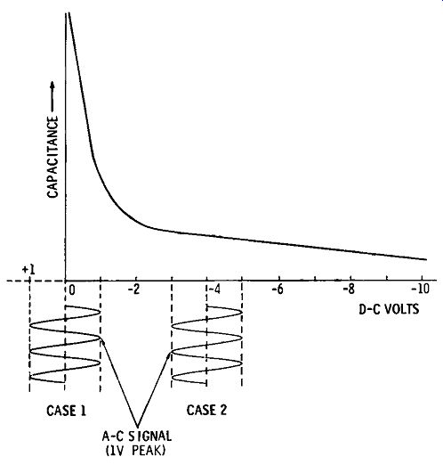
Fig. 2-3. Operating point.
In the choice of operating point, there are other considerations than avoiding forward bias, however. Note from the shape of the reverse capacitance curve in Fig. 2-3 that the slope of the curve is different at virtually each of the operating-voltage points. Accordingly, the waveform of varactor current will be different, since the reactance will vary at a different rate at each operating point.
In many applications which include combined alternating and direct current, the a-c component is kept much smaller than the d-c bias; otherwise, the a-c component will deter mine the varactor capacitance. In the circuit of Fig. 2-1, for example, terminals X-X normally are connected to some sort of a-c circuit in which the capacitance of the varactor will be utilized, and the a-c signal voltage in that circuit must be substantially lower than d-c control voltage V, or the direct current will be less effective than the alternating current in determining the varactor capacitance. It is well to restrict the peak value of the a-c voltage to not more than 1/10 of the d-c voltage. The sum of d-c voltage and peak a-c voltage must not exceed the maximum working voltage of the varactor.
Waveform
Alternating voltages applied to varactors are perhaps most often sine waves. But this is not mandatory. A signal voltage may also be a nonsinusoidal or pulse (square, rec tangular, sawtooth, triangular, etc.) type. In general, the only precautions to be observed in the use of such signals are those which apply to use of the same signal with any capacitor of the same Q, capacitance, and voltage rating as the varactor, and/or the circuit in which it is connected.
MULTIPLE OPERATION
Large-capacitance varactors are not available at present.
While a single varactor is seen in most circuits, the desire to connect two or more of these units in parallel to obtain higher capacitance for some applications may arise. Parallel operation is feasible if the following considerations are observed.
Total Capacitance The total capacitance is the sum of the individual capacitances:
Ct= C1 + C2 + C3 ••• +C0 •
The minimum (as well as the maximum) capacitance is multiplied. Thus, three varactors, each of which covers the range 50 to 200 pf for a given voltage variation, wi L1, in parallel combination, pro vide a capacitance range of 150 to 600 pf.
Voltage versus Capacitance
The voltage-versus-capacitance curve will be a composite of the curves of the individual varactors. This means that the shape of the curve for the parallel combination will depart from that of a single varactor to the extent that the capacitances of the individual units differ from each other at vari ous voltage points. At a given voltage along the curve, the capacitance of the parallel combination will be the sum of the capacitances of the individual varactors. A special curve should be plotted for a parallel combination.
Total Reactance
The reactance of the combination is less than that of any one of the varactors: where, Ct is the total capacitance.
If the individual reactances are known, the total reactance can be calculated by the formula:
Parallel Resistance
When varactors are connected in parallel, their parallel resistance (R,,) components, as well as their capacitance components, are effectively connected in parallel, as shown in Fig. 2-4. The total resistance of this combination is less than either of the individual parallel resistances. Using Ohm's law, it is computed:
SERIES RESISTANCE NEGLECTED
(A) Equivalent circuit. (B) Simplified equivalent circuit.
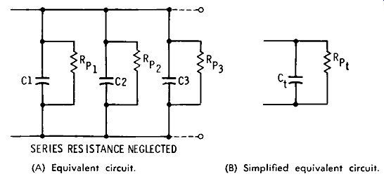
Fig. 2-4. Parallel connection of varactors.
Total Leakage Current
Since the parallel resistance of the combination is less than that of any one of the varactors, the leakage current at a given voltage must, by Ohm's law, be higher than that of any one of the varactors. The total leakage current is the sum of the individual currents:
VARACTOR AND CONVENTIONAL CAPACITOR IN COMBINATION
A varactor often furnishes the total capacitance in a circuit. Occasionally, however, the varactor supplies only a part of the capacitance, the remainder coming from a conventional fixed or variable capacitor in parallel or series with the varactor.
(A) Parallel.
(B) Series.
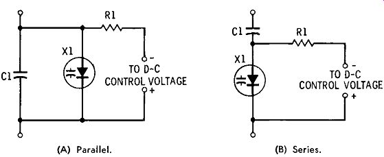
Fig. 2-5. Varactor and conventional capacitor in combination.
Parallel Circuit
Fig. 2-5A shows the parallel connection of a varactor and a conventional capacitor. Here, varactor X1 shunts fixed capacitor C1 The varactor thus acts as a trimmer. A d-c control voltage, for varying the varactor capacitance, is applied through the high isolating resistance of R1. The total capacitance of this combination at any value of the varactor capacitance is: where, Ct is the total capacitance, C1 is the capacitance of the fixed capacitor, Cd is the capacitance of the varactor.
The minimum and maximum capacitances of the combination can be calculated by adding the minimum ( or maxi mum) capacitance of the varactor to the fixed capacitance.
Capacitor C1 may also be variable. As such it may be used as a trimmer which is preset to limit the capacitance range of the varactor.
Series Circuit
Fig. 2-5B shows the series connection of the combination.
As in the previous circuit, a d-c control voltage for varying the varactor capacitance may be applied through the high isolating resistance of R1. Here, the fixed capacitor acts as a padder for the varactor, or as a d-c-blocking capacitor, de pending on the use to which the combination is put. The total capacitance of this circuit must be less than that of either of the capacitors (conventional or varactor). That is, at any value of varactor capacitance, the total capacitance is calculated by the formula: where, Ct is the total capacitance, C1 is the capacitance of the fixed capacitor, Cd is the capacitance of the varactor.
When C1 is fixed and is equal to or less than the maximum value of Cd, it will reduce the capacitance range of the varactor. Capacitance C1 may also be variable, whereupon it may act as a padder which may be preset to limit the capacitance range of the varactor.
When a fixed capacitor is connected in series with a varactor for protective purposes (i.e., to block direct current from an external circuit, as shown in Fig. 2-1), its capacitance is chosen very high with respect to the varactor capacitance. A fixed capacitor equal to 1000Cd is a good choice to ensure minimum effect on both varactor capacitance and the capacitance range.
VARACTOR-TUNED CIRCUITS
One of the basic uses of the varactor is the tuning of circuits. Figs. 2-6 and 2-7 show simple arrangements for d-c tuning single-section LC and RC circuits. Such combinations as these may be used as building blocks for more complicated circuits.
AC INPUT (A) Series resonant.
DC INPUT
+ (B) Parallel resonant.
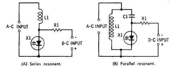
Fig. 2-6. Varactor-tuned LC circuits.
Series-Resonant LC Circuit
Fig. 2-6A shows a series-resonant circuit. Here, the frequency is determined by the inductance of L1 and the capacitance of the varactor. The varactor and d-c control voltage are chosen to provide the capacitance range needed to tune the circuit over the desired frequency range. The high resistance of isolating resistor R1 usually will serve to block r-f energy and prevent its passage into the d-c supply from the resonant circuit; however, a radio-frequency choke sometimes is used instead. (An iron-core choke is used at audio frequencies.) As in other series LC circuits, a step-up voltage appears across the capacitor at resonance; this volt age must not be high enough to override the d-c control volt age or to exceed the mwv of the varactor.
Parallel-Resonant LC Circuit
Fig. 2-6B shows a parallel-resonant circuit. As in the series circuit, the frequency is determined by the inductance of L1 and the capacitance of the varactor. The varactor and d-c control voltage are chosen to provide the capacitance range needed to tune the circuit over the desired frequency range. The blocking capacitance must be very much higher than the varactor capacitance ( usually 1000 X) for lowest reactance, so that the varactor, rather than the fixed capacitor, tunes the circuit. At radio frequencies, isolating resistor R1 may be replaced with a radio-frequency choke, and at audio frequencies with a suitable iron-core choke.
(A) Low-pass.
(B) High-pass.
(C) Parallel.
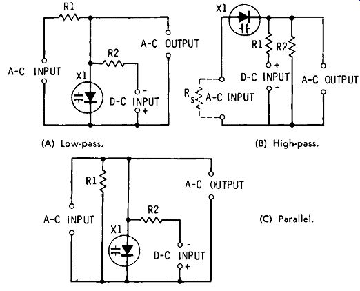
Fig. 2-7. Varactor in RC tuned circuits.
Series RC Circuits
Fig. 2-7A shows a series RC circuit of the low-pass filter type. Here, the frequency response is determined by the resistance of R1 and the capacitance of the varactor. The d-c control voltage is applied through isolating resistor R2, which must be very much higher in value than R1 (usually R2 is several megohms and R1 only a few kilohms). Fig. 2-7B shows a series RC circuit of the high-pass filter type. The frequency response of this circuit is determined by the resistance of R2 and the capacitance of the varactor.
The d-c control voltage is applied through isolating resistor R1, which must be very much higher in value than R2. The high-pass circuit requires that a d-c return path (for the control voltage) be provided by the a-c source, as indicated by the phantom resistor, R., in the illustration. When several such RC sections are operated in cascade, this path is automatically provided by the preceding output resistor (R2 in Fig. 2-7B).
Parallel RC Circuit
Fig. 2-7C shows a parallel RC circuit in which the frequency is determined by the capacitance of varactor X1 and the resistance of R1. Here, as in Fig. 2-7A, the d-c control voltage is applied through isolating resistor R2, which must be very much higher in value than R1.
VARACTOR AS FREQUENCY MULTIPLIER
The varactor has distinguished itself particularly well in frequency multiplication (harmonic generation). In this application, it performs doubling, tripling, quadrupling, or even higher frequency multiplication in transmitters and laboratory instruments more simply than do tubes and transistors.
Fig. 2-8 shows the basic arrangement of a varactor multi plier. Radio-frequency energy is fed into the stage at a frequency f. This frequency is transmitted to the varactor by pass filter 1 ( often a simple, fixed-tuned, series-resonant circuit). Because of the nonlinear response of varactor X1, the current Ur) due to the input voltage is distorted, containing a number of harmonics. The desired harmonic, a multiple nf of the input frequency, is selected by a second filter (pass filter 2) and transmitted (as harmonic current I_nf) to the output terminals. For doubling, the second filter is tuned to twice the input frequency (i.e., n = 2) ; for tripling, to three times the input frequency, etc.
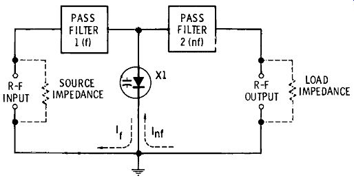
Fig. 2.8. Varactor frequency multiplier.
Because the varactor contains very little series resistance and thus handles reactive power principally, it dissipates little power-its losses are very low. It is this feature that gives the varactor multiplier its high efficiency (90 percent for the varactor doubler, compared with an ideal 50 percent for tubes and transistors in the same function). A further advantage of the varactor multiplier is its freedom from the need for a power supply; the r-f signal itself is the only power required.