The ability of the varactor to tune an LC circuit suits it to various general-
and special-purpose receiver applications. In fact, it is in this area that
some of the earliest practical applications of the voltage-variable capacitor
were devised.
Automatic corrective retuning processes, such as automatic frequency control (afc), are particularly benefited by the simplicity of the varactor. Vhf and uhf amplifiers employing varactors such as the one in Fig. 3-1, offer low-noise operation, high gain, and compactness.
The eventual development of small, multiple varactors doubtless will revolutionize receiver tuning by eliminating the ganged variable capacitor. In microminiature receivers, all front-end varactors could receive their d-c tuning voltage through a single miniature rheostat.
TUNING REQUIREMENTS AND CONSIDERATIONS
It is a comparatively simple matter to tune a coil, such as an r-f oscillator, amplifier, or detector coil or transformer winding, with a varactor. This was shown in the previous section (Fig. 2-6). However, sharp tuning demands a high-Q varactor. The varactor capacitance-and capacitance range-must be sufficient to cover the desired frequency band with the available range of control voltage.
If a wide frequency band must be covered, a high d-c volt age may be required in order to reduce the capacitance sufficiently to-tune to the high-frequency end. This introduces the additional varactor requirement of high maximum working voltage (mwv). Another problem is posed by the fact that since Q decreases as voltage increases, the needed high-frequency selectivity may be sacrificed.
Courtesy TRW Semiconductors

Fig. 3-1
A small high-Q, low-leakage varactor (TRW V947) in proprietary D0-7 package.
Tuning Range
In an LC tuned circuit, the frequency ratio varies directly as the square root of the capacitance ratio:
/max _
/min -
Restated and illustrated, this means simply that a varactor must, for example, have a capacitance ratio of 4:1 if a frequency ratio of 2 :1 is to be achieved.
Tuning the standard broadcast band in one sweep requires a capacitance ratio (C_max/C_min) of approximately 9 :1, and with presently available coils and loops, Cwax must be 350 to 365 pf. A varactor for broadcast-band tuning must meet each of these requirements. There is little problem at higher frequencies, however. Standard varactors are easily adapted. The values of Cwax and of the ratio Cmu./Cmln of many presently available varactors easily permit complete coverage of bands higher than the broadcast band. For example, an inexpensive 47-pf varactor with a control voltage of 0-10 volts and an appropriate inductor will continuously tune any of the ham radio bands between 80 and 10 meters.
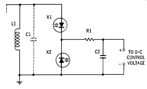
Fig. 3-2. A balanced-varactor tuned circuit.
Balanced-Varactor Tuning
If a tuning varactor is forward biased by the signal during a part of the cycle, its leakage will increase momentarily and its Q may suffer. Moreover, significant harmonic energy is generated as the varactor is biased alternately positive and negative. The circuit shown in Fig. 3-2 avoids these disadvantages by employing two varactors connected back to back, in place of the simpler single-varactor tuned-tank circuit shown previously. The d-c control voltage is applied simultaneously to both varactors through the high resistance of R1. When the r-f signal is applied (Fig. 3-2), the identical varactors X1 and X2 are driven into high capacitance and low capacitance alternately. The net capacitance in the circuit is approximately constant and properly is determined by the d-c control voltage, rather than by the signal amplitude.
A disadvantage of the balanced circuit is the reduction of tank capacitance, due to series connection of the varactors; the total capacitance of the X1-X2 combination is:
However, the reduction can be offset by choosing varactors with a value equal to twice the desired tank capacitance.
If varactor tuning is to cover only a portion of a frequency band, the varactor unit may be used as an incremental tuning section ("band-spreader") and a fixed trimmer installed, like C1 in Fig. 3-2.
In this circuit, R1 is the usual high-resistance isolating resistor, and it acts in conjunction with C2 to form a radio frequency filter.
Multistage Tuning
Two or more stages may be gang tuned, as shown in Fig. 3-3, by applying the d-c control voltage simultaneously to all of them. Closely matched varactors are demanded for each stage, in order that all will exhibit the same capacitance si multaneously. Only two stages are shown in Fig. 3-3, but the d-c control (tuning) line can be extended for use with other such stages.
(A) Single-varactor circuit.
(B) Balanced-varactor circuit.
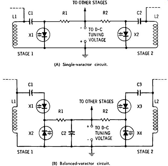
Fig. 3-3. Ganged tuning.
Fig. 3-3A shows two gang-tuned r-f stages of the single varactor type. Here, L1 and L2 are shown as single coils but may also be the secondary windings of r-f transformers. C1 and C2 are d-c-blocking capacitors which not only protect varactors X1 and X2 from any d-c component present in the receiver circuit, but also prevent a short circuit of the d-c control signal by L1 and L2. The d-c tuning voltage is applied to varactor X1 through isolating resistor R1, and to X2 through R2. Trimmers may be connected in parallel with L1 and L2, or these coils may be slug-trimmed, as desired, for range coverage.
Fig. 3-3B shows the corresponding two-gang tuning of r-f stages of the balanced-varactor type. Aside from the employment of matched varactors X1 to X4 in the balanced circuit, the arrangement is the same as that shown in Fig. 3-3A.
D-C Tuning Voltage
The d-c voltage used for tuning must be very clean; other wise the frequency will be swept at a rate corresponding to the frequency of any ripple, hum, or other noise riding the d-c tuning voltage, and the sweep width will be governed by the peak amplitude of the interfering voltages.
The d-c voltage must also be constant; otherwise slow or abrupt detuning will occur, depending on how the voltage fluctuates. This means that it must be supplied by an excellently regulated source.
Correct polarity of varactor and of the d-c voltage must be preserved, to ensure proper operation and to prevent damage to the varactor.
Why Varactor Tuning?
A question might arise as to the feasibility of using varactor tuning in the first place:
"Is adjusting a potentiometer to control the tuning voltage very different from adjusting a variable capacitor?"
The answer depends on the circumstances. A miniature potentiometer, of course, is a great deal smaller than a plate type variable capacitor, dramatically so when the capacitor has two to four sections. In some miniaturized equipment, there is no room for even the smallest tuning capacitor, whereas a flat, miniature potentiometer can be fitted in. If a special tuning curve (such as logarithmic) is required, it sometimes can be obtained with an easily acquired potentiometer much more readily than a variable capacitor with specially cut plates. If a proportional d-c voltage ( error signal, remote-tuning scheme, etc.) is already available, the varactor offers a way to use it without having to adopt motor-driven tuning. The varactor also provides a means of ganged tuning without mechanical coupling, which means that stages can be positioned on a chassis for maximum efficiency, convenience, and compactness, rather than having their location dictated by the shape and size of a multisection tuning capacitor.
An additional application which is simplified by the varactor is "scan tuning," in which a portion of the r-f spectrum is automatically swept repetitively. Band sweeping may be accomplished by applying a reverse-polarity saw tooth-wave tuning voltage to the varactor in any of the tun ing circuits shown in Figs. 2-6, 3-2, or 3-3. The sawtooth voltage may be applied by itself or in series with a d-c bias.
The frequency of the LC tank will be swept through the tuning range by each sawtooth, at a rate corresponding to the sawtooth frequency. A goodly number of voltage-vari able capacitance diodes are catalogued as tuning varactors.
AUTOMATIC FREQUENCY CONTROL
In automatic frequency control (afc), a receiver which has drifted off frequency is returned automatically in accordance with a d-c error voltage developed by the detector.
Afc is particularly useful in fm tuners.
Fig. 3-4 shows a varactor afc circuit applied to an f-m receiver. Here, a small varactor, X1 (the nominal capacitance is immaterial), is connected in parallel with the oscillator tank (L1-C1) in the receiver front end, through blocking capacitor C2. As the d-c bias on this varactor is varied, the oscillator frequency, and therefore the receiver tuning, will be varied accordingly. The operating point of the varactor is set at 5 to 8 d-c volts by the bias voltage obtained through the voltage divider (R1-R4). This bias is obtained from a well-regulated point in the receiver power supply.
The d-c tuning voltage (a kind of error signal) is obtained from the discriminator stage of the receiver and is applied to the varactor through an r-f filter consisting of resistors R2 and R3, capacitors C4 and C5, and r-f choke L2.
After installation of the afc circuit, the receiver must be realigned to compensate for the presence of the varactor across the oscillator coil. Subsequently, as long as the receiver remains tuned to a station to which it has been set, no d-c voltage is delivered by the discriminator to R3. If the receiver detunes, however, a proportional d-c voltage is applied to varactor X1 through the filter (C4, C5, R2, R3, and L2). This voltage changes the varactor capacitance in pro portion to the amount of detuning, and this change in capacitance retunes the receiver by changing the oscillator frequency the proper amount.
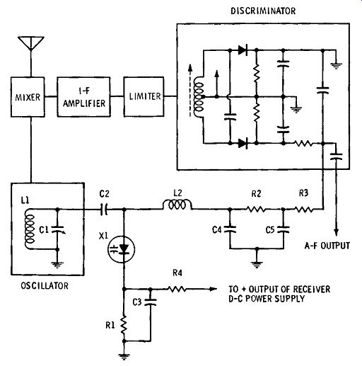
Fig. 3-4. Afc applied to an f-m receiver.
R-F AMPLIFIER (PRE-SELECTOR)
In uhf and microwave receivers, low-noise r-f amplification may be provided by a varactor operated from a radio frequency power supply (pump). Sensitive amplifiers of this type have been used in the deep-space tracking program of NASA and were prominent in Project Echo. For a description of the varactor r-f amplifier, see Section 5.