The voltage-variable nonlinear capacitance of the varactor may be used to amplify a signal. The kind of amplifier that results belongs to that class of devices known as reactance amplifiers. Other types of reactance amplifiers are the magnetic amplifier and the electrostatic amplifier. The distinguishing peculiarity of every reactance amplifier is its need of a high-frequency AC power supply. It differs in this respect from tube and transistor amplifiers, which are operated from a DC supply.
As an electrostatic device, the varactor amplifier offers the advantages of high input impedance, very low noise, circuit simplicity, instant operation (no warm-up), physical ruggedness, and small size (in most instances). The idea of electrostatic amplifiers was not introduced by the varactor, however; such amplifiers based on nonlinear (ferroelectric) ceramic capacitors have been known for a number of years.
BASIC PRINCIPLES
How the variable reactance of a varactor is exploited for amplification may be understood by reference to the simple demonstration circuit in Fig. 5-1. In this arrangement, the AC power source excites varactor X1 through isolating transformer T1 and blocking capacitor C1. Current resulting from this AC excitation flows through load resistor RL, the output device. Now, if a DC voltage of correct polarity is applied to the signal input terminals, it will shift the operating point of the varactor, changing the latter's capacitance and reactance and shifting the current through RL to a new level. Because very little signal current is needed to obtain a large change in the current through RL, amplification results.
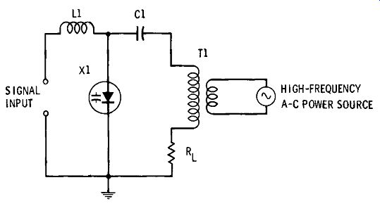
Fig. 5-1. The basic varactor amplifier.
Choke coil L1 blocks the AC power from the signal input terminals. If, instead of direct current, an AC signal is applied to the signal input terminals, the RL (output) current will vary in sympathy with the input-signal alternations (for best results, the power-supply frequency must be at least ten times the highest signal frequency). If a DC voltage is applied in series with the AC signal, the former will permit the operating point to be set along the steepest part of the varactor response curve. This results in maximum amplification.
Even this rudimentary circuit is capable of appreciable gain, especially if the output circuit is tuned to the power supply frequency. Practical varactor amplifiers are some what more sophisticated in configuration, however, and are of two types: resonant-slope and parametric.
RESONANT-SLOPE AMPLIFIERS
This type of amplifier is so named because it utilizes the steep slope of a resonant LC circuit in which the varactor is the signal-variable capacitor. It is also known as a carrier amplifier, capacitor amplifier, and dielectric amplifier.
AC Amplifiers
Fig. 5-2A shows the circuit of a single-ended AC amplifier.
Here, varactor X1 resonates inductor L1 at the frequency of the h-f power supply which is coupled to this inductor through L2. The resonance curve is shown in Fig. 5-2B. Protective blocking is provided by capacitor C1, which must be chosen for low impedance at the power-supply frequency.
Inductance L1 and DC bias voltage Ede are chosen so that the operating point (see Ed~ in Fig. 5-2B) will fall along the steepest straight portion of the response curve, some what off resonance. [1] When an AC signal, E.e (see pattern A in Fig. 5-2A) then is applied through transformer T1, it will fluctuate the bias above and below the value Ede (pattern B). This, in turn, will fluctuate the varactor capacitance and cause the L1- X1 tank to be detuned above and below point X (Fig. 5-2B), resulting in amplitude modulation of the h-f voltage across the tank (see pattern C). Note, however (from pattern C and from "amplified signal" in Fig. 5-2B), that this signal is several times larger than input signal Eac, showing that amplification has taken place. We need only to demodulate this signal to recover E.e amplified, and this is done by means of the conventional diode (X2), which de livers the amplified output signal shown in pattern D. In this circuit, radio-frequency choke L3 keeps h-f supply current out of transformer T1 and the battery, and radio frequency choke L4 and C2 in combination remove the h-f component from the modulated signal (pattern C). For audio-frequency signals, T1 and T2 are iron-core transformers; for radio-frequency signals, they are air core.
Like tubes and transistors, varactors may be operated push-pull for increased output and reduced harmonic distortion. Fig. 5-3 shows a push-pull AC amplifier circuit. Note that the upper and lower halves of this circuit are identical with the single-ended circuit in Fig. 5-2A and operate in the same manner. For symmetrical operation, the similar components must be matched electrically (i.e., C1 = C2, C3 = C4, X1 = X2, X3 = X4, L3 = L4, and L5 = L6).
---------------
1. Note that "straight" here does not mean linear, but un-curved. The sector must be straight although nonlinear, for without nonlinearity there is no amplification.
----------
Also for symmetry, transformers T1 and T2 and inductor L1 are center tapped.
(A) Circuit.
(B) Performance.

Fig. 5-2. A single-ended varactor AC amplifier.
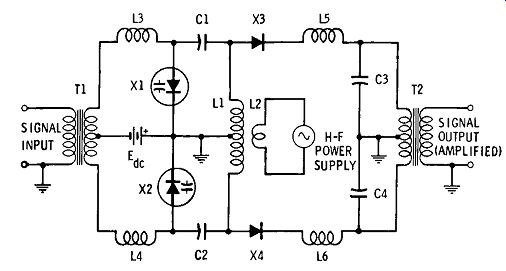
Fig. 5-3. Push-pull varactor amplifier.
PARAMETRIC AMPLIFIER
The parametric uhf and microwave amplifier has figured prominently in the space exploration program, largely be cause the low-noise properties of this amplifier (superior to those of any tube or transistor) make it usable at very low signal levels. It also provides high gain.
In the resonant-slope amplifier described in the preceding section, the varactor offers reactance to the power supply, and the signal varies this reactance at a lower-frequency rate. In the parametric amplifier, on the contrary, the varactor offers reactance to the signal, and the power supply varies this reactance at a higher-frequency rate while at the same time it adds power to the signal. It is as if a weak signal in the resonant-slope amplifier switches the higher power from the power supply into the load, and in the parametric amplifier the power supply switches the signal into the load while simultaneously adding power to it. In the parametric amplifier, the power supply is said to "pump" the varactor; hence it is called the pump.
Fig. 5-4A shows the functional arrangement of the parametric amplifier (Fig. 5-4C is a practical amplifier employing a resonant cavity). The pump voltage is a reversed volt age (e.g., only negative half-cycles), so when it is maximum it minimizes the capacitance of the varactor. Now, if the signal and pump are applied in such a way that the varactor ...
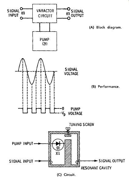
Fig. 5-4. Principle of the parameter amplifier.
(A) Block diagram. (B) Performance. (C) Circuit.
... is already fully charged by the signal when the pump-pulse peak arrives, the charge (Q) remains constant but the varactor voltage (V) increases because the capacitance (C) has been pushed down (V = Q/C). This increases the power in the varactor circuit, i.e., power is delivered to the load when the varactor capacitance is lowest. For this action to take place, a pump-voltage peak must occur at the instant that the signal voltage on the varactor is at its positive peak and again when it is at its negative peak. This requires that the pump be both properly phased with respect to the signal, and also that its frequency be twice the signal frequency.
Fig. 5-4B shows these relations. When the phase relations are as shown, minimum varactor capacitance occurs at positive and negative peaks of the signal cycle, and maximum capacitance at the zero-signal points. (If we could mechanically open and "close" a two-plate capacitor in the same sequence at the signal frequency, we could get amplification in the same way that the pumped varactor provides it.) A parametric amplifier of the type just described is said to operate in the degenerate mode.
The need for tight control of phase in the degenerate parametric amplifier has given rise to another design in which the pump operates at a frequency other than twice the signal frequency. This involves the use of an idler. Fig. 5-5 shows the functional arrangement of this type, with the ...
X1
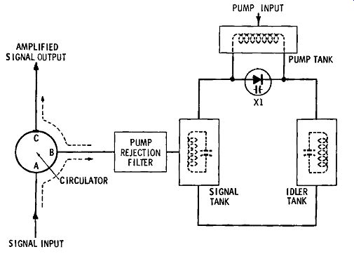
Fig. 5-5. Parameter amplifier with idler.
... signal tank, pump tank, and idler tank represented as lumped LC circuits (dotted lines). In this arrangement, a three-port microwave circulator is used for input and output coupling. With the system in operation, a third frequency the idling frequency-is produced, which is equal to the difference between signal and pump frequencies. Varactor X1 couples the three tanks in the circuit which handle these frequencies.
The signal to be amplified is applied to port A of the circulator, and the latter transmits this signal, through port B, to the signal tank. A mixture of the amplified signal and an idler-frequency signal then would appear at port B, but the idler frequency is removed by the pump rejection filter, so only the amplified signal remains, and it is transmitted, through port C, to the load.
DC AMPLIFIER
Fig. 5-6A shows the circuit of a curious DC varactor amplifier of the resonant-slope type. With DC input and output signals, this circuit provides a current gain of 500, power gain of 50, and voltage gain of 0.1. In its transformation of high input resistance (10 megohms) to low output resistance (2000 ohms) at power gain and voltage loss, it resembles a DC cathode follower and is useful as such whenever its 10:1 voltage reduction can be tolerated.
When powered from a 30-MHz power supply (transistor crystal oscillator operated at 3 volts, the circuit can employ a 47- or 56-pf varactor. At 1-volt DC input, the amplifier circuit draws 0.1 µ,a from the signal source (DC input power equals 0.1 µ,w). This input current is due entirely to current through input resistor R2, which is provided for the purpose, since the varactor draws only a leakage current of approximately 0.02 µ,a. With 1-volt signal input, the amplifier delivers an output of 0.1 volt and 50 µ,a into a 2000-ohm load ( DC output power equals 5 µ,w). The tank coil (L2) of the amplifier circuit is tuned entirely by varactor X1 Protective DC blocking is provided by capacitor C1. Radio-frequency energy is transmitted into this tank through link-coupling coil L1 The varactor capacitance (and thus the tank frequency) is proportional to the DC signal voltage, applied through isolating resistor R1. The r-f voltage across L2 is therefore proportional to the DC signal voltage. The r-f voltage is rectified and filtered by diode X2 and capacitor C2 to provide a DC output. Resistor R1 and capacitor C3 serve as a radio-frequency filter to block power-supply r-f energy from the DC input terminals.
Fig. 5-6B shows the response of the circuit. Note that the choice of a high power-supply frequency (30 MHz) enables the L2- X1 tank to be completely tuned and detuned by varying the DC input signal voltage between zero and 1 volt. As shown in this illustration, when input signal voltage Ede equals zero, the circuit is completely detuned. At this time, the r-f tank voltage is zero and so is the DC output. But when Ede equals 1 volt, the r-f tank voltage and DC output are maximum (this is ensured by adjusting the slug on L2 for resonance when Ede equals 1 volt). Because of the curvature of the varactor response, the DC output voltage varies nonlinearly with respect to the DC input voltage.
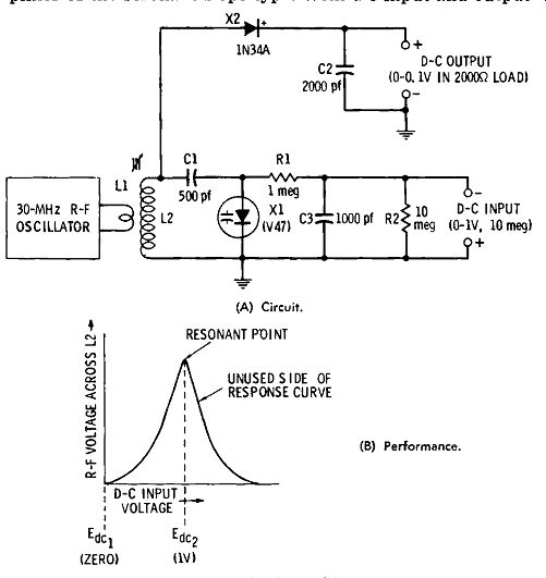
Fig. 5-6. The DC amplifier. (A) Circuit. (B) Performance.