As a unique variable capacitor, the varactor is often in valuable in special-purpose
test instruments. In such applications, it replaces hand-tuned and motor-driven
capacitors or more complicated tube or transistor circuitry used to simulate
these capacitors. As in its other applications, the varactor in instrumentation
requires little or no attention after installation, and it offers simplicity,
compactness, and ruggedness.
ABSORPTION WAVE-METER
A DC-controlled varactor can tune an absorption wave meter satisfactorily. This is very convenient when, for reasons of compact construction, very high frequency opera tion, or elimination of strays, even a small variable capacitor is undesirable.
Fig. 6-1 shows a DC-tuned wavemeter circuit. The basis of any wavemeter is a plug-in coil and variable capacitor; here L1 is the plug-in coil and varactor X2 is the variable capacitor. The capacitance of the varactor is adjusted by means of a continuously variable DC voltage obtained by setting potentiometer R2. The inductance of L1 is chosen so that the varactor capacitance range will afford cover age of the desired frequency band. In this circuit, DC blocking capacitor C1 prevents coil L1 from short circuiting the DC supply. Isolating resistor R1, r-f choke L2, and by pass capacitor C3 form an r-f filter to block r-f tank voltage from the DC input terminals.
Increasing the DC tuning voltage by advancing potentiometer R2 decreases the varactor capacitance and increases the resonant frequency of the L1-X2 tank. (When L1 is loosely coupled to the r-f signal source, resonance is indicated by peak deflection of the DC microammeter, which receives rectified current from the conventional diode, XL) A dial attached to the potentiometer accordingly may be calibrated to read directly in megahertz. If a direct indication of resonance is not needed (i.e., resonance will be indicated instead by the effect of the wavemeter on the circuit to which it is coupled), the meter circuit ( X1, C2, and the meter) may be omitted.
The DC tuning voltage must be well regulated, otherwise the frequency calibration of the potentiometer will be disturbed and the instrument will be unstable in operation. (A simple zener-diode regulator with battery or AC supply is adequate in most cases.) Also, the amplitude of the r-f signal picked up by the wavemeter must be low enough to pre vent overriding the DC tuning voltage. Loose coupling will afford the needed protection.
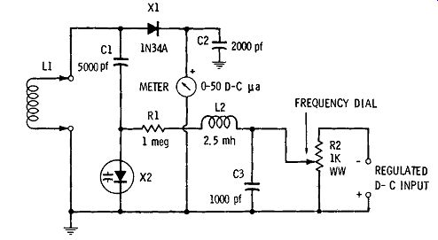
Fig. 6-1. Absorption wavemeter.
REMOTE-TUNED FIELD-STRENGTH METER
Somewhat similar to the absorption wavemeter just de scribed is the simple diode-type field-strength meter. Like the wavemeter, the latter also consists of an LC tank followed by a diode-rectifier-type meter. At resonance, the deflection of the meter is proportional to the strength of the received signal.
The varactor makes it possible to tune a field-strength meter at a distance. This is important when the instrument must be located in close quarters or when the presence of the operator's body would distort the measurements-as in the immediate field of an antenna. Both the tuning adjust ment and the indicating meter may be placed at a remote station connected to the pickup unit of the instrument by a shielded cable.
PICKUP ANTENNA
REMOTE PICKUP CONTROL STATION
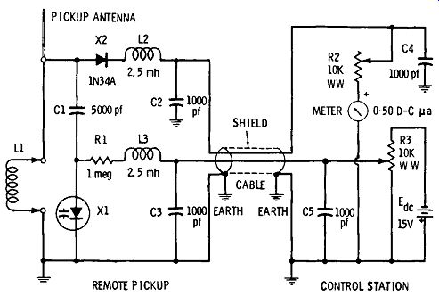
Fig. 6-2. Remote-tuned field-strength meter.
Fig. 6-2 shows the circuit of a remote-tuned field-strength meter. As in the wavemeter, the tank consists of a plug-in coil and varactor ( L1 and X1). the inductance of the coil is chosen so that the varactor capacitance range (with the available DC voltage spread) will provide coverage of the desired frequency band. Capacitor C1 provides DC blocking, to prevent the coil from short circuiting the varactor DC voltage. The r-f tank voltage is rectified by conventional diode X2, whose output is fed through the cable to the DC microammeter at the distant control station.
The shielded cable connecting the remote pickup unit to the control unit (station) has two inner conductors. One of these conducts direct current from diode X2 to the meter; the other conducts direct current from tuning potentiometer R3 to varactor X1 The shield provides the common (ground) connection between the two units and must be connected to an earth ground at both ends.
There are two r-f filters in the pickup unit. One of these (comprised of isolating resistor R1, r-f choke L3, and by pass capacitor C3) keeps radio frequencies out of the tuning-voltage source, and the other (comprised of r-f choke L2 and bypass capacitor C2) removes radio frequencies from the DC output of rectifier diode X2. Radio-frequency bypassing is provided at the control station by C4 and C5.
Potentiometer R3 affords smooth tuning of the remote tank, and its dial may be calibrated directly in megahertz, if desired. The 15-volt battery ( Ede) will serve in most in stances to tune the general run of varactors used for this purpose (nominal capacitances between 12 and 100 pf), but a higher voltage is needed for very-wide-band tuning.
At resonance, the meter gives peak deflection. Adjustment of the series rheostat, R2, keeps the pointer from pinning.
The scale of this meter may be graduated directly in micro volts or millivolts, if desired, but the response is nonlinear, crowding at the low end of the scale because of the combined nonlinearity of diode X2 and varactor X1 This necessitates an individual calibration for each instrument and the drawing of a special scale.
The r-f signal voltage applied to the varactor should not exceed 0.1 volt peak, to circumvent its overriding the DC tuning voltage. This can usually be managed successfully by correctly positioning the pickup unit in relation to the signal source, and/or gauging the pickup antenna.
HARMONIC INTENSIFIER FOR FREQUENCY STANDARD
Secondary frequency standards employing 100-kHz crystal oscillators are widely used. With or without multivibrators, such oscillators supply harmonics for calibration points far into the r-f spectrum.
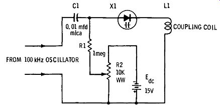
Fig. 6-3. A harmonic intensifier for frequency standard. FROM 100 kHz OSCILLATOR;
COUPLING COIL
Unfortunately, however, the output of the simpler 100 kHz oscillator is almost a pure sine wave, which means that the harmonics beyond about 1000 or 2000 kHz are too weak to use. Some designers have inserted a germanium diode in the oscillator output circuit and used its nonlinear low for ward current to distort the 100-kHz wave and thus produce stronger harmonics. But, because the diode is a power-consuming resistive component, a better course is to use a varactor-a high-Q reactive component which consumes virtually no power.
Fig. 6-3 shows the circuit of a harmonic intensifier for use with a standard-frequency oscillator. Here, varactor X1 is in series with the standard-frequency oscillator output and coupling coil L1 (which is a few random turns of insulated wire for coupling the signal into a receiver or other device under test). Capacitor C1 provides DC blocking; i.e., it protects the intensifier circuit from any direct current in the oscillator output, and prevents coil L1 from short circuiting the intensifier bias, Ede• Varactor X1, because of its non-linear response, delivers a distorted (harmonic-rich) current to coil L1.
A varactor bias circuit is provided: 15-volt battery Ede, potentiometer R2, and isolating resistor R1. This allows biasing the varactor at will to the particular operating point at which a desired harmonic will be accentuated. Some high order harmonics, especially when the oscillator output amplitude is high, will be strengthened most when the varactor DC bias is zero (potentiometer R2 turned all the way down). The proper bias value-or even the need of any bias-for a particular desired harmonic is determined by experiment.
In individual cases, some improvement in operation is obtained by shunting coil L1 with a variable capacitor to form a tank at the desired harmonic frequency.
RF SWEEP OSCILLATOR
A swept-frequency r-f oscillator or signal generator is required for visual display of the response curve of a tuned ...
SELF-EXCITED; 5000 pf; OSCILLATOR CIRCUIT; SAWTOOTH VOLTAGE INPUT
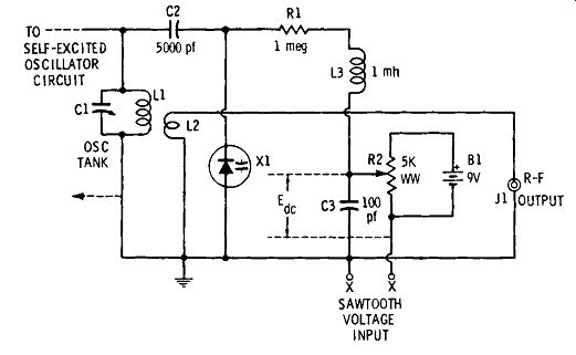
Fig. 6-4. An r-f sweep oscillator.
... circuit. This instrument is a type of frequency-modulated oscillator. A straight c-w oscillator which lacks this feature may be provided with swept output by means of the circuit shown in Fig. 6-4. (An explanation of frequency modulation via a varactor was given in a previous section.) In Fig. 6-4, L1 is the tank coil of the r-f oscillator, and C1 is the oscillator tuning capacitor. L2 is the output coupling coil. (In an individual oscillator, the arrangement may be somewhat different: the output may be capacitance-coupled, rather than inductive-coupled, and some type of attenuator is inserted ahead of output jack Jl.) Varactor X1 is connected across the tank, through DC-blocking capacitor C2, and thus can tune the oscillator some distance above and below the frequency determined by L1 and the setting of C1.
A sawtooth wave applied to terminals X-X will sweep the varactor bias, Ede, repetitively over a range determined by Ede and the peak amplitude of the sawtooth voltage. This, in turn, will sweep the varactor capacitance and the oscillator frequency. Bias Ede is adjusted by means of potentiometer R2, to tune the oscillator to the desired resonant frequency when the sawtooth is at one-half of its peak voltage. A single rise of the sawtooth then sweeps the oscillator output from zero (or "practical zero") through the resonant peak and back to zero.
For radio and television alignment and the testing of many components, the sawtooth frequency may be 60 or 120 Hz. Sawtooth waves may be obtained from a special signal generator, from a transistor oscillator built for the purpose, or from a special pair of output terminals on some oscillo scopes used for visual testing. Because the varactor response is nonlinear, the frequency axis of the displayed resonance pattern will be nonlinear. This will require a special, corre sponding frequency calibration of the horizontal axis of the oscilloscope used; otherwise, a nonlinear sawtooth wave must be used to compensate for the nonlinearity of the varactor.
SIGNAL CONVERTER
In scientific and industrial instrumentation, high-gain DC amplification often is obtained by means of a three-step process: (1) the DC signal to be amplified is first changed into a proportionate AC voltage by means of a converter, then (2) this AC voltage is amplified by a high-gain AC amplifier which can be made more stable than a comparable DC amplifier, and finally (3) the amplified AC volt age is rectified to give an amplified DC output. Some of the converters used for this purpose are vibrator-type choppers, transistor-type choppers, photoelectric choppers, magnetic modulators, Hall-effect modulators, magnetoresistive modulators, and diode-bridge modulators.
Fig. 6-5A shows a three-step amplifier system in which the converter is a varactor bridge. This bridge changes the DC input signal into a proportionate AC voltage which then is presented to the input of the AC amplifier. Finally, the amplified AC output is rectified by conventional diode X3, and the resulting amplified DC output voltage developed across resistor R2.
(B) Equivalent circuit.
(A) Layout.
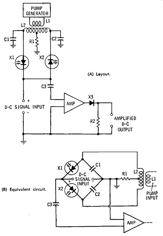
Fig. 6-5. Varactor signal converter for an instrument amplifier.
In Fig. 6-5B, the converter portion of the circuit has been redrawn to show its bridge configuration more clearly. The four arms of the bridge are formed by capacitors C1 and C2 and varactors X1 and X2. The bridge is powered by an h-f pump voltage delivered by the balanced secondary (L2) of the bridge input transformer. The bridge output is coupled to the amplifier input by blocking capacitor C3.
The reactances of C1, C2, X1, and X2 are chosen such that the bridge is balanced at these values and no pump signal reaches the amplifier. When a DC input signal is applied, however, it changes the varactor capacitance and thereby unbalances the bridge, switching a proportionate amount of pump voltage into the amplifier input. The advantages of the varactor bridge are : (1) practically zero power consumption, (2) extremely high input resistance offered to the DC signal, (3) extremely low noise, and ( 4) conversion gain.
The pump frequency is not critical, so long as it can be accommodated by the amplifier. The gain supplied by parametric amplifier action in the bridge reduces the gain requirement of the amplifier somewhat.
ELECTRONIC DC VOLTMETER
The resonant-slope DC varactor amplifier discussed in a previous section is utilized in Fig. 6-6A to provide an electronic DC voltmeter circuit. This instrument behaves in a manner similar to the vacuum-tube voltmeter and its transistorized counterpart. Its input resistance is 10 megohms, and its DC ranges are 0-1.5, 0-15, 0-150, and 0-1500 volts.
Unlike the vtvm and transistor voltmeter, this instrument has no zero adjustment.
The h-f power supply is a transistor oscillator operated from a 27.255-MHz Citizens Band crystal and, link-coupled to the tank comprised by coil L2 and varactor X1 The tank is operated on the low side of resonance, so that a 1.5-volt DC input tunes the circuit exactly to resonance (trimmed initially by means of the L2 tuning slug) and deflects the meter to full scale. The selectivity of the tank is high enough that the circuit detunes completely when the DC voltage is removed, and the meter reads zero. Initial adjustment consists merely of applying an accurately known 1.5-volt DC input (with range switch S1 set to its 1.5-volt position) and adjusting the slug on L2 for exact full-scale deflection of the meter. The coupling between L1 and L2 must be rigid and the oscillator DC power supply must be well regulated (a zener diode with battery supply suffices), for the instrument to be stable.
Because of the nonlinear response of varactor X1 and diode X2, the voltmeter scale is nonlinear, crowding at the low end. Fig. 6-6B shows the meter readings for various in put voltages; hence, a typical calibration.
If a very-low-leakage varactor is used, the input resistance of the instrument can be increased to 100 megohms by multiplying the values of each resistor (R2 through R5) by ten.
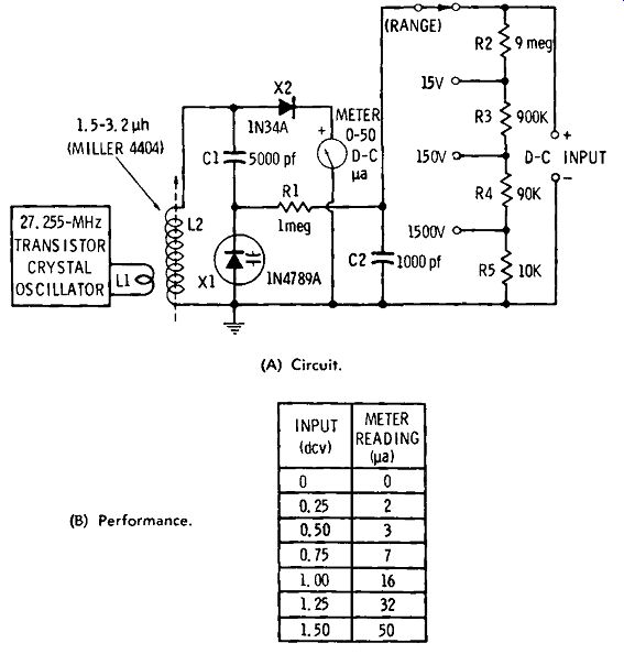
Fig. 6-6. Electronic DC voltmeter. (A) Circuit. (B) Performance.
One might question the use of this varactor circuit when the transistor and its DC power supply might be removed from the crystal oscillator and used directly as a "vtvm." The answer is that the high input resistance of 10 to 100 megohms would not be obtained unless a more expensive field-effect transistor were used.